

Product display

Absolute value encoder AL-E5C10 series
Summary:
Classification:
Absolute value encoder
Related Documents:
- Summarize
- Technical data
- Related downloads
-
- Commodity name: Absolute value encoder AL-E5C10 series
This product is used for angle, length measurement, and positioning control in industrial systems.
1. Overview
1.1 Manual Instructions
This manual mainly describes product information. For operational safety, please carefully read the manual before operating the device!
In addition, local accident prevention regulations and general safety rules must be followed.
1.2 Warranty Statement
Warranty period is 18 months, calculated from the delivery date.
2. Transportation and Storage
2.1 Transportation and Unpacking Safety Instructions
Professional transportation packaging (packaging boxes, etc.) is used. Do not throw, impact, or fold.
2.2 Transportation Inspection
Upon receipt, please immediately check whether the delivery contents are complete and whether there is any transportation damage. If damage is found:
- Do not accept the goods or only accept them under the condition of reserving the right of recourse;
- Record the extent of the damage in the transport documents or delivery note;
- Immediately file a complaint.
2.3 Storage
Storage should meet the following conditions:
- Keep dry and dust-free;
- Do not expose to corrosive media;
- Avoid mechanical impact.
3. Product Features
3.1 Applications
This product is used for angle, length measurement, and positioning control in industrial systems.
4. Product Information
4.1 Product Selection
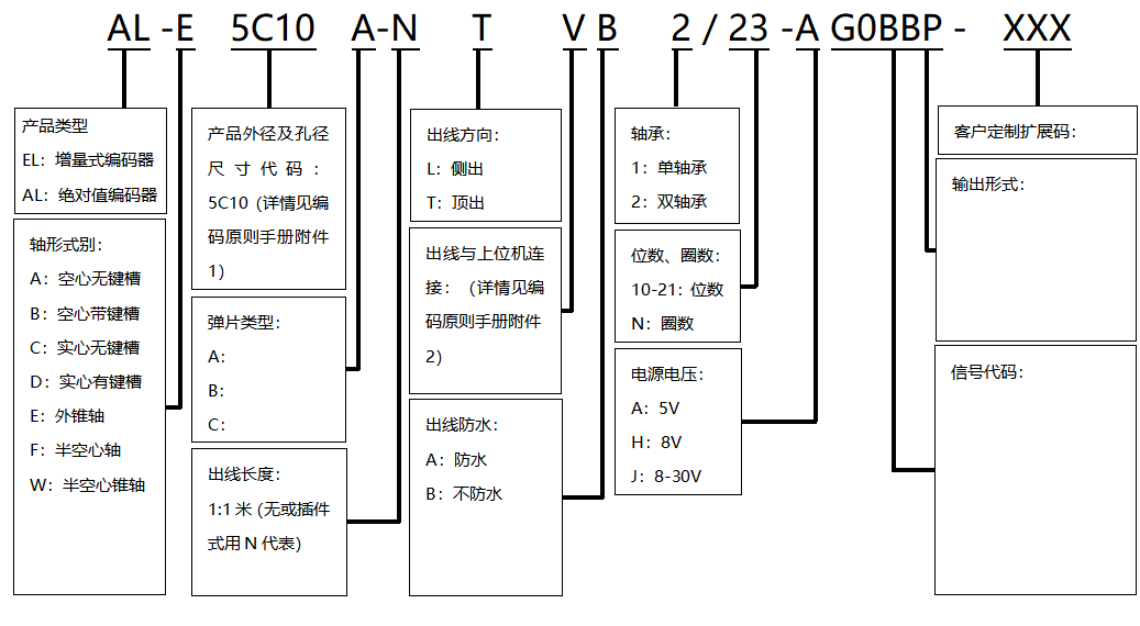
4.2 Dimensional Drawing
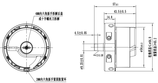
Figure 1 Installation Size Diagram (unit: mm)
4.3 Technical Data
Supply Voltage
DC5±0.25V
Current Consumption
<140mA
Communication Frequency
≤16KHz
Baud Rate
1.25Mbps
Resolution
Maximum support 8388608 (23Bit)
Communication Circuit
Differential drive (RS485)
Absolute Positioning Accuracy
-(Depends on the motor shaft rotation accuracy)
Repeatability
< ±5 arc seconds
Insulation Resistance
50MΩ
Interface
RS485
Auxiliary Function
Fault Warning: *Electromagnetic Environment Warning* Overspeed Warning*Temperature Warning
Speed
6000r/min(Max)
Axial Load
20N
Radial Load
30N
Vibration Resistance
100m/S², 200Hz, 2h in each XYZ direction
Impact Resistance
100m/S², 10ms
Starting Torque
0.002N.M(Max 25℃)
Permissible Shaft Deviation
Axial: - Axial Runout: <0.1mm
Radial: ±0.1mm Radial Runout: <0.1mm
Ambient Temperature
Operating: -25℃~85℃;Storage: -30℃~100℃
Ambient Humidity
95%RH
Protection Level
IP50
Weight
Approx 204g
 4. Installation and Removal Instructions
 4.1 Installation Instructions

Figure 1 Installation Diagram
①: Use the accessory 4MM hexagon wrench to unscrew the encoder top cover screws counterclockwise and remove the back cover.
②: Push the encoder into the host installation hole. After the tapered shaft and the tapered hole are tightly fitted, insert the accessory M5*50 bolt into the encoder tapered shaft, and use the accessory 4MM hexagon wrench to tighten it clockwise (tightening torque 5-5.5Nm) to fix it coaxially with the traction machine.
③: Use the accessory 2MM hexagon wrench to tighten the clamping ring tightening screw clockwise (tightening torque 0.6-0.8Nm) so that the clamping ring is tightly fitted and fixed to the traction machine body.
Note: After installing the encoder, connect the matching cables to the encoder terminals, confirm the direction and press slowly. After installing the cables, tighten the encoder rear cover with screws and press down on the cable shielding.
4.2 Disassembly Instructions

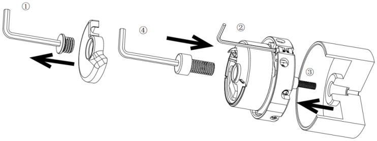
Figure 2 Disassembly Diagram
①: Use the accessory 4MM hexagon wrench to unscrew the encoder top cover screws counterclockwise and remove the rear cover. Pull out the encoder cable.
②: Use the accessory 2MM hexagon wrench to rotate the clamping ring fastening screw counterclockwise, separating the clamping ring from the hoist body.
③: Use the accessory 4MM hexagon wrench to rotate the M5 bolt in the tapered shaft counterclockwise by 1-2 turns.
④: Use the accessory 4MM hexagon wrench to turn the M10*20 stud bolt clockwise into the center hole of the encoder. After encountering resistance, forcefully tighten it to loosen the encoder. Remove the M10 stud bolt, then unscrew the M5 bolt and remove the encoder.
5. Connection Method
5.1 Wiring Definition
Positive Power
Negative Power
485(B)
485(A)
PE
Signal
C-
A-
0V
R-
6. Communication Method
6.1 E²PROM Communication Specification
Unit
Address
Description
Remarks
Address Range of Read/Write User Parameters
0~0xDE
User Parameter Field
This address field can be used to store user parameters.
0xDF
Configure ENID
Numerical Value Can Be Set
Read-Only Address Range
0xF0~0xF1
Product Code
This address field is used to store manufacturer parameters; it is read-only, and writing is invalid.
0xF2~0xF3
Product Operating Status
0xF4~0xFF
Reserved
Maximum Erasable Times
100000 times
Number of Executable Operations
6.2 Frame Format
Each data frame is divided into several bytes, and the transmission and reception of each byte is implemented by one start bit, eight data bits, and one stop bit, with the low bit first and the high bit last. The terms used in data frame transmission are shown in the following table:
Unit
Description
Remarks
CF
Control Field
Used to identify different command types.
SF
Status Field
Obtain the encoder status through this part.
DF
Data Field
Encoder position data
ADF
Address Field
Accessible encoder address
EDF
E2PROM Field
Content of the specified address
CRC
CRC Check
Polynomial: x8+1 (All data XOR, except CRC)
6.3 Position Data Reading
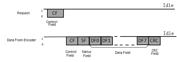
Note: The number of DF data depends on the different CFs.
6.4 Write E²PROM
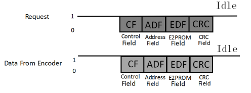

*The request frame and the return frame have the same content.
6.5 Read E²PROM
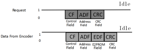
*The return frame adds the content of the accessed address.
6.7 Control Field (CF)
CF There 1 bytes, categories and contents are shown in the table below:
CF Category
CF Content
Remarks
Read Data
ID0(0×02)
Absolute position information reading (CF+SF+ABS+CRC)
ID2(0×92)
Encoder ID information reading (CF+ENID+CRC)
ID3(0×1A)
Read all data (CF+SF+ABS+ID+ABM+ALMC+CRC)
Write E²PROM
ID6(0×32)
8-bit "user data" can be written to the data corresponding to the specified address. After sending the instruction format, 20 μs Within s, the encoder sends back data; do not communicate with the encoder during this process.
Read E²PROM
IDD(0×EA)
8-bit "user data" can be read from the specified Address. After the instruction format is sent, 20 μs s, the encoder sends back data; do not communicate with the encoder during this process.
Reset
ID7(0×BA)
This reset instruction requires sending the instruction 10 times continuously at intervals of no less than 62.5 μs s to reset all fault flags.
ID8(0×C2)
This reset instruction requires sending the instruction 10 times continuously at intervals of no less than 62.5 μs s at intervals to continuously send the instruction 10 times, resetting any single-turn position to zero. Even after power is turned on again, this position will remain at the reset position data.
6.8 Status Field(SF)
SF consists of 1 byte, with each bit defined as shown in the table below:
Bit Number
Description
Remarks
Bit0
Rsvd
All "0"
Bit1
Rsvd
Bit2
Rsvd
Bit3
Rsvd
Bit4
Counting Error
Encoder position calculation error; this bit will be set to 1.
Bit5
Rsvd
0
Bit6
Rsvd
0
Bit7
Rsvd
0
6.9 Data Field (DF0~DF7)
Depending on the CF type, DF has a different number of bytes, as shown in the table below:
CF Type
DF0
DF1
DF2
DF3
DF4
DF5
DF6
DF7
ID0
(0×02)
ABS0
ABS1
ABS2
ID2
(0×92)
ENID
ID3
(0×1A)
ABS0
ABS1
ABS2
ENID
00
00
00
ALMC
ID7
(0×BA)
ABS0
ABS1
ABS2
ID8
(0×C2)
ABS0
ABS1
ABS2
Note: 1. ABS0~ABS2 are the low, middle, and high bits of the encoder's single-turn position respectively. For a 23-bit encoder, the highest bit of ABS2 is 0, and the rest are valid bits;
2. ENID is the encoder ID, with a value of 0×17 (23-bit);
3. ALMC is the encoder fault flag, see the fault description for details.
ALMC fault see the table below:
Bit
0
1
2
3
4
5
6
7
Definition
Over-sp
eed
“0”
Counting
Error
“0”
“0”
“0”
“0”
“0”
Each fault flag is described in the table below:
Fault Name
Function Description
Solution
Over-speed
In 5V power supply mode, the speed is greater than 7200RPM
Power on again
Counting Error
Single-turn information calculation error
Power on again
6.10 Timing Diagram
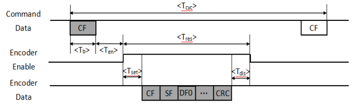
Name
Symbol
Minimum
Typical
Maximum
Unit
Description
Command cycle period
Tcyc
105
μs
Data byte time
Tb
8
μs
Encoder enable delay time
Ten
1.6
2
μs
Encoder response time
Tres
50
52
μs
ID0: 6 bytes data
90
92
μs
ID3: 11 bytes data
34
36
μs
ID8: 4 bytes data
Encoder data set-up delay time
Tset
1.2
1.7
μs
Encoder disable delay time
Tdis
1.2
1.6
μs
Contact Information
Changchun Shenghang Electronics Co., Ltd.
Company Exchange Tel: 0431-89543335 0431-89543336
Company Email: sh@ccshdz.com
Company Website: www.ccshdz.com
Company Address: B8, B9 Buildings, Phase 1, Beihubo Science and Technology Park, Beihubo Science and Technology Development Zone, Changchun, Jilin Province
-
Power Supply Voltage
DC5±0.25V
Current Consumption
<140mA
Communication Frequency
≤16KHz
Baud Rate
1.25Mbps
Resolution
Maximum Support 8388608 (23Bit)
Communication Circuit
Differential Drive (RS485)
Absolute Positioning Accuracy
-(Depends on motor shaft rotation accuracy)
Repeat Positioning Accuracy
<±5 arc seconds
Insulation Resistance
50MΩ
Interface
RS485
Auxiliary Function
Fault Warning: *Electromagnetic Environment Warning* Overspeed Warning*Temperature Warning
Speed
6000r/min(Max)
Axial Load
20N
Radial Load
30N
Vibration Resistance
100m/S², 200Hz, XYZ direction for 2h each
Shock Resistance
100m/S², 10ms
Starting Torque
0.002N.M(Max 25℃)
Allowable Input Shaft Deviation
Axial: - Axial Runout: <0.1mm
Radial: ±0.1mm Radial Runout: <0.1mm
Ambient Temperature
Operating: -25℃~85℃;Storage: -30℃~100℃
Ambient Humidity
95%RH
Protection Grade
IP50
Weight
Approximately 204g
-
Instruction Manual Template for AL-E5C10-NTVB2-23-AG0BBP Series.docx
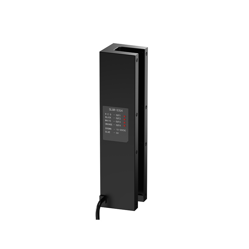
Related Products
Product Consulting

Service Hotline:
Company switchboard:0431-89543335 0431-89543336
Sales Department:0431-80829999 0431-86071111
Department of International Trade:0431-89543339
Company E-mail:sh@ccshdz.com
Company address: Building B8, Phase I, Beihu Science and Technology Park, Beihu Science and Technology Development Zone, Changchun City, Jilin Province


Copyright: Changchun Shenghao Electronics Co., Ltd.
